Mallory Ignition Wiring Diagram Ford Iv

4 Wire Ignition Switch Diagram 1 With Images Kill Switch

Pin By Satren On 300 Turbo Diesel Intercooler Diesel Map Turbo
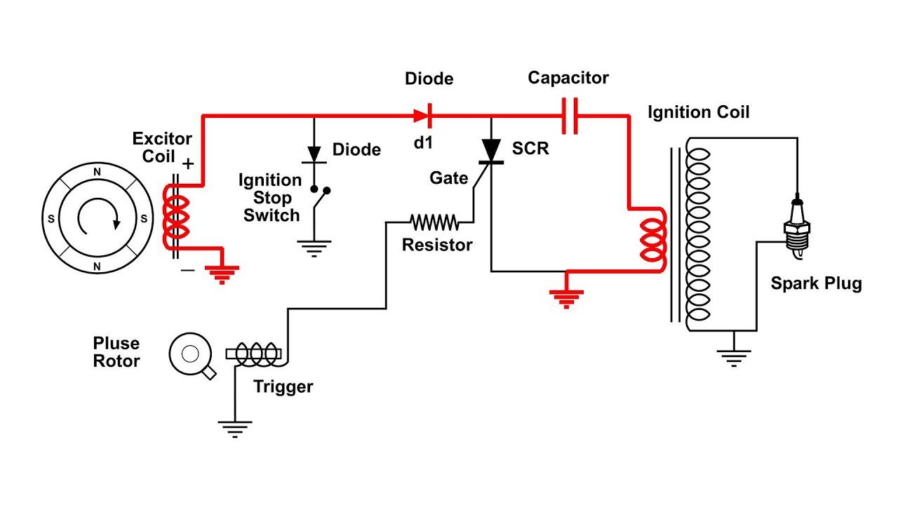
Cdi Capacitor Discharge Ignition Circuit Demo Youtube

Simple Wiring Diagram Vw Dune Vw Dune Buggy Dune Buggy Vw Engine

New Golf 4 1 9 Tdi Wiring Diagram Diagram Diagramsample

Dacia Car Radio Stereo Audio Wiring Diagram Autoradio Connector
Routing wires the hyfire wires should be routed away from direct heat sources such as exhaust manifolds and headers and any sharp edges.
Mallory ignition wiring diagram ford iv. If your vehicle has a ballast resistor in line with the coil wiring it is recommended to bypass it. 641 4 641 6 641 8 642 643 and 644 will not function with the hyfirefi vi electronic ignition controls. Mallory pro tach i iv and vi the rpm needle and shift light will work with the hyfire vi. Wiring procedure step 1 refer to figure 3 ensure that your vehicle is equipped with a ground cable between the engine block and firewall 10 gauge or larger is required.
By the late 1960 s the detroit plant had become too small and boots mallory began moving his father s company to carson city nevada in 1969. It shows the components of the circuit as streamlined forms as well as the power and also signal links between the tools. However the tach s proportional controller that limits rpm will not function with the hyfire vi. Step 2 choose one method listed below for wiring the hyfirefi iv electronic ignition control 2a 2b or 2c 2a wiring method using adapters and harnesses sold separately special wiring adapters and harnesses simplify the installation of the hyfirefi iv electronic ignition control into newer vehicles.
Magneto ignition systems super mag ii sprintmag super mag read online or download pdf mallory diagrams on pages 2 and 3 for all additional wiring. Next you need to purchase a gm hei module. Hyfirefi iv electronic ignition control. Locate one long red wire and one long black wire at the end plate of the hyfire iv electronic ignition control.
Mallory ignition wiring diagram free wiring diagram collection of mallory ignition wiring diagram a wiring diagram is a simplified standard pictorial depiction of an electrical circuit it shows the. 1951 ford 8n wiring diagram. Mallory proportional rpm limiter part nos. Currently working on changing my ignition to a mallory super mag with i have wiring diagram for all the components but none of them exactly aug 31 please help.
641 4 641 6 641 8 642 643 and 644 will not function with the hyfire vi electronic ignition controls. Collection of mallory ignition wiring diagram. Ddec iv ecm wiring diagram. However the tach s proportional controller that limits rpm will not function with the.
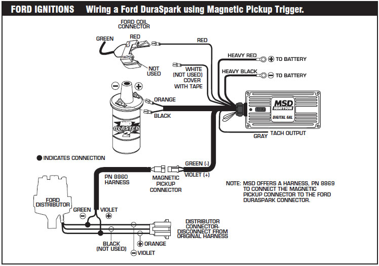
A wiring diagram is a simplified standard pictorial depiction of an electrical circuit. Mallory proportional rpm limiter part nos. Mallory supplied much of the original equipment ignition components for ford through 1948. So will a msd or mallory distributor with a ford style magnetic pickup these are the distributors without a built in module.
Ask for one from the 1970 s. Even today mallory continues to build performance ignition products for ford motor company vehicles. Mallory pro tachfi i iv and vi the rpm needle and shift light will work with the hyfire fi vi.


Switchback Led Turn Signals On 5th Gen 4runner Step By Step

9393 4l80e Trans Wiring Diagram Transmission Science Memes

Ek 5338 Coil Ballast Resistor Wiring Diagram Msd 6al Wiring
How To Install An Msd 6a Digital Ignition Module On Your 1979 1995

Mf 7816 Mallory Hyfire 6853m Wiring Diagram Schematic Wiring

Clazzio Seat Cover Tacoma Double Cab 2020 Black Leather 2123

Cartaholics Golf Cart Forum E Z Go Wiring Diagram Controller