Mallory Ignition Hyfire Wiring Diagram

Mf 7816 Mallory Hyfire 6853m Wiring Diagram Schematic Wiring

Km 1681 Wiring Diagram Mallory Comp 9000 Wiring Diagram Mallory

Gd 9382 Mallory Magnetic Breakerless Distributor Wiring Diagram
914world Com Mallory Hyfire

Mallory 685 Ignition Wiring Camaro Forums At Z28 Com

Mallory Tach Wiring Pro Wiring Diagram

Routing wires the hyfire wires should be routed away from direct heat sources such as exhaust manifolds and headers and any sharp edges.
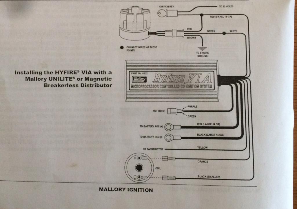
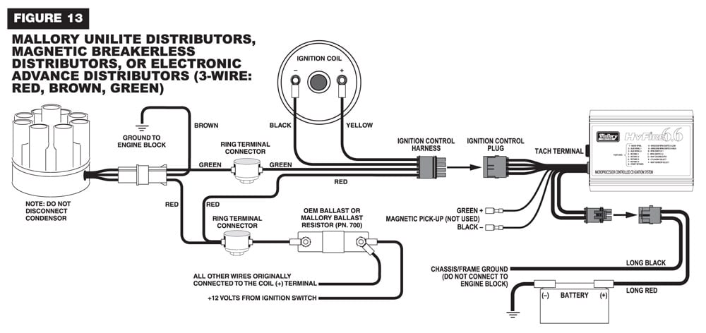
Mallory ignition hyfire wiring diagram. Installation instructions 3 mallory www mallory ignition com 915 857 5200 fa 915 857 3344 ballast resistor. The mallory hyfire ignition. Mallory s promaster coil p n can also be used as well as most stock coils or aftermarket coils the yellow wire on the hyfire 6a ignition control provides a trigger signal for use the chart at right as a starting point. 6852m 6 a and 6853m 6 al installation instructions form 1522tl general information the features of the hyfire 6 a and hyfire 6 al are the same with one exception the hyfire 6 al includes a single stage.
Now my question is where does the stock tach lead hook up to does it go to the coil or to the coil hook up on the ignition box. Unilite distributor vacuum chamber and the carburetor. Mallory hyfirefi vi electronic ignition controls are not compatible with distributorless systems or positive ground applications. 1 hyfirefi vi electronic ignition control part no.
With a vintage design for that classic look the hyfire looks as good as it per. Collection of mallory ignition wiring diagram. Mallory hyfire wiring question nastyz28 com. A familiar name in ignition performance is back.
Parts included in this kit. If your vehicle has a ballast resistor in line with the coil wiring it is recommended to bypass it. 6851 basic for applications triggered by points mallory electronic ignition distributor all models original equipment electronic ignition ampli fi ers and magnetic trigger pulses magnetic pickup distributor or crank trigger ignition. I ve got the older style mallory ignition amplifier and have already downloaded a wiring diagram to hook up to a unilite.
A wiring diagram is a simplified standard pictorial depiction of an electrical circuit. Mallory hyfire ignition wiring diagram file pdf book only if you are registered here. 685 advanced hyfire vi ignition system part no. The purpose of an ignition ballast resistor between the ignition switch 12v and the ignition coil positive terminal is to restrict current flow through the ignition coil.
It shows the components of the circuit as streamlined forms as well as the power and also signal links between the tools.
Zb 7771 Vw Electronic Distributor Wiring Diagram Free Diagram

La 3254 Mallory Unilite Distributor Wiring Diagram Schematic Wiring

Twin Plug 3 2 Motor Pelican Parts Forums

Msd 6al 2 Wiring Diagram Blog Wiring Diagram

Mallory Instructions Hyfire 206a 6al Wiring Diagram 6852m 6853m

Mallory Hyfire Ignition Youtube

Ss 8391 Mallory Promaster Coil Wiring Diagram Free Image Wiring
Nitrous Oxide Installation Zex Perimeter Nitrous Kit Fordmuscle
