Mallory 685 Wiring Diagram

Mallory 685 Ignition Wiring Camaro Forums At Z28 Com
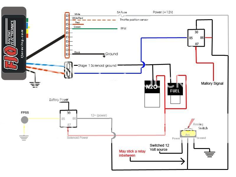
Wiring Mallory 685 With Pic Ls1tech Camaro And Firebird Forum
Mallory Ignition 685

Aa 3903 Wiring Diagram On 3 Wire Ballast Resistor Wiring Diagram

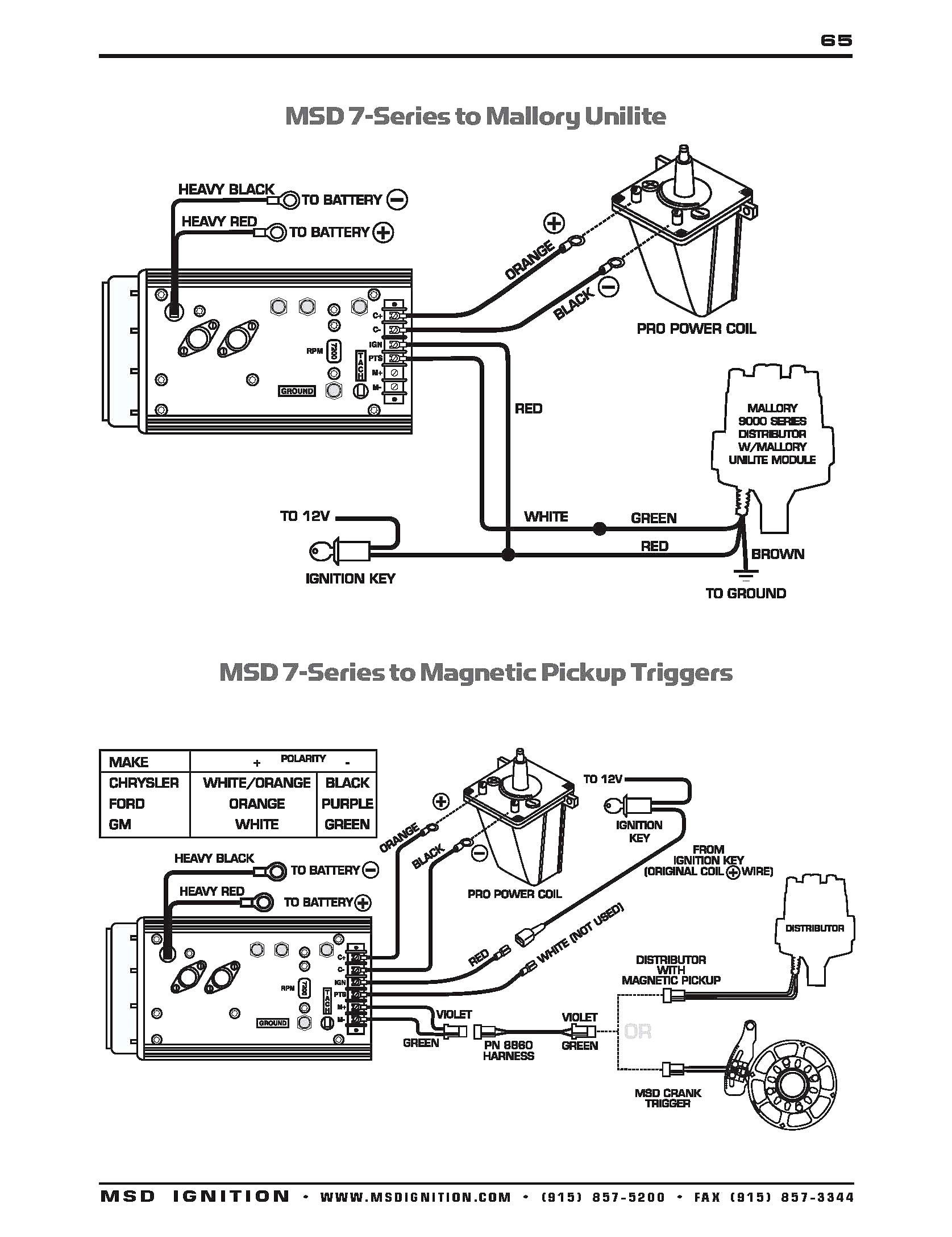
Mallory Unilite Wiring Diagram Sbc Diagrams Schematics Inside
Sponsors Area

The rpm limiter in the hyfire vi part no.
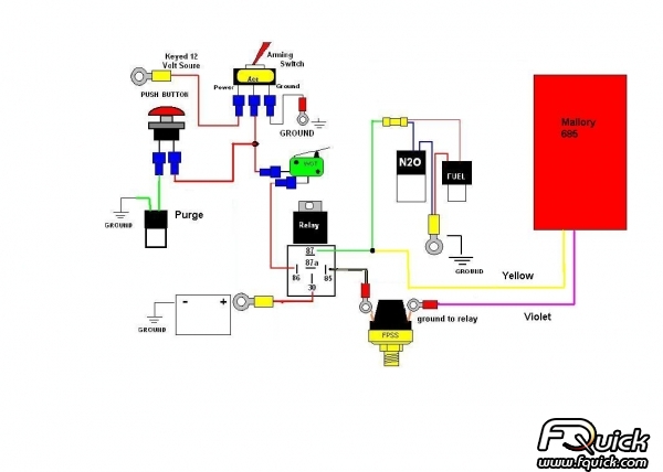
Mallory 685 wiring diagram. 2 customer reviews for mallory ignition 685 mallory ignition ignition boxes. The rpm limiter in the hyfire fi vi part no. 685 will not work properly with odd fi re or semi even fi re v6 applications. Mallory hyfire vi electronic ignition controls are not compatible with distributorless systems or positive ground applications.
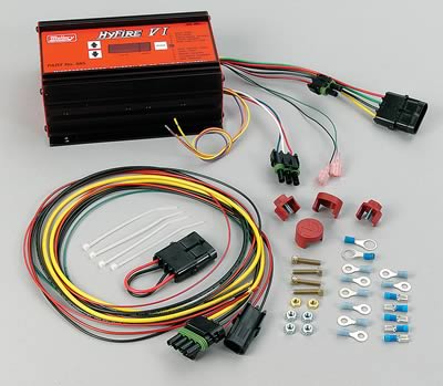
629 630 631 685 692 or 697 distributor wire harness part no. Parts included in this kit. Arguing with msd i put. The mallory hyfire 6851 ignition system has the same basic connections as the 685 ignition system.
685 will not work properly with odd fire or semi even fire v6 applications. Man i went thru this with my mallory the parts store sold me the wrong harness i eventually got a set of good instructions off of a msd site since the only difference is the tach wire. 1 hyfire vi electronic ignition control part no. Mallory 685 ignition wiring diagram additionally mallory hyfire 6853m wiring diagram bodyarch co in addition mallory ignition 685 free shipping on orders over 99 at in addition n20 wiring schematic chevy impala ss forum moreover besides additionally also together with further in addition.
1 hyfirefi vi electronic ignition control part no. 29349 12v ignition switch ignition ballast resistor ring terminal connectors part no. Omc ignition switch diagram chevy silverado wiring diagram mallory ignition wiring diagram chevy mallory hyfire ignition wiring diagram. Mallory hyfirefi vi electronic ignition controls are not compatible with distributorless systems or positive ground applications.
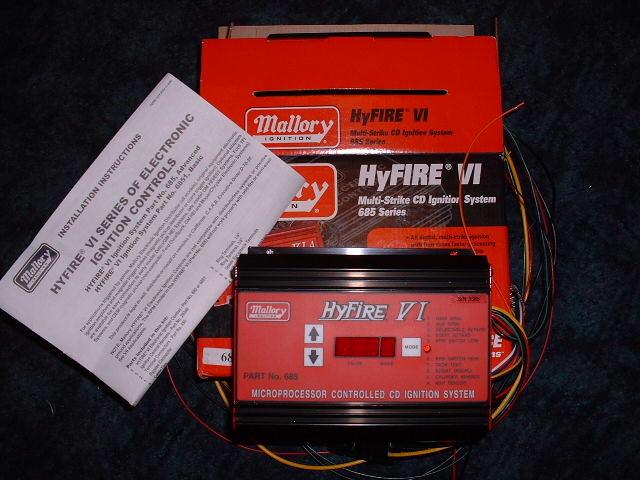
I get a link to a pic here in just a second of a 685 wiring diagram. 5 star 4 star 0 3 star 0 2 star 0 1 star 0 see all 2 reviews. 6852m 6 a and 6853m 6 al installation instructions form 1522tl general information the features of the hyfire 6 a and hyfire 6 al are the same with one exception the hyfire 6 al includes a single stage. Mallory unilite distributor installation instructions.
6852m 6 a and 6853m 6 al installation instructions form 1522tl general information the features of the hyfire 6 a and hyfire 6 al are the same with one exception the hyfire 6 al includes a single stage. Installed on my mm. Mallory 685 wiring diagram. This rpm switch is controlled by two rotary dip switches that are located behind an access plate on the top of the unit see the illustration below.
Figure 1 unilite wiring diagram using ballast resistor note. After 2 msd digital 6 boxes failed. Parts included in this kit.

Mallory Distributor Wiring Diagram In 2020 With Images Diagram
Fg 7165 As Well Wiring Diagrams Additionally Msd Nitrous Wiring
41f Mallory 8548201 Hei Wiring Diagram Wiring Library
Nitrous Related Wiring Page 2 Ls1tech Camaro And Firebird

Wrg 8282 Horn Relay Diagram Wiring

Mallory Mag Wiring Diagram Pro Wiring Diagram

The Way Of Microplastic Through The Environment Application Of

Pin On Patrick Lothrop
